
Introduction
In the previous article Characteristics and Key Points of Controller Area Network (CAN bus), we discussed the basic features of CAN, its types, differences, and the contents of data frames.
Traditionally, data transfer is carried out by defining specific IDs and specifying what each of the 8 bytes of data represents, detailed in a DBC file for further explanation and decoding.
The CAN protocol itself only defines how to transfer data on the network without specifying the content and format of the data. Therefore, higher-level protocols (HLP) such as CCP/XCP, CANopen, AUTOSAR, and J1939 are introduced to meet different needs and application scenarios.
For example, without using HLP in CAN, we might define ID 0x100 to indicate the first 4 bytes as vehicle speed, ranging from 0 to 150 km/h; the last 4 bytes indicate gear information, where 1000 indicates P gear and 0100 indicates D gear. Different manufacturers have their own definitions, usually recorded in a large Excel sheet or DBC file for decoding.
Introduction to SAE J1939
The SAE J1939 protocol is developed by the Society of Automotive Engineers (SAE) in the USA. Some of its features include:
- Uses a 29-bit extended identifier.
- Standardizes CAN transmission rates to 250 kbps or 500 kbps.(*)
- Supports point-to-point addressing (node addressing) and global addressing (message addressing).
- Multi-packet messages can transmit up to 1785 bytes.
- Network access control through its own network management.
- Standardized messages for overall vehicle communication.
- Allows manufacturer-specific message definitions.
- Defines its own diagnostic interface.
Since J1939 mainly uses extended frames for communication, the identifier is expanded from 11 bits to 29 bits, allowing for advanced information such as priority, data page, group number, etc.
SAE J1939/14 Physical Layer Standard first published in 2011, defines a speed of 500 kbps. SAE J1939/22 CAN FD Data Link Layer defines CAN FD as the transport layer for J1939 implementation. In reality (≈2024), most still adopt CAN 2.0 as the standard transport layer.
Packet Format
The SAE J1939-21 document defines the 29-bit CAN ID structure as shown in the table below, totaling 29 bits:
| Parameter Group Number (PGN) | ||||||
| Priority | Extended Data Page | Data Page | PDU Format | PDU Specific | Source Address | |
|---|---|---|---|---|---|---|
| Abbreviation | P | EDP | DP | PF | PS | SA |
| Bit Length | 3 bits | 1 bit | 1 bit | 8 bits | 8 bits | 8 bits |
Priority: Uses 3 bits to determine the message priority in network transmission, with lower values indicating higher priority, ranging from 0 to 7. The default priority for all control-related messages is 3, while the default priority for other information, proprietary, request, and acknowledgment messages is 6. When a PGN is added to the application layer documents, a recommended value is assigned, and the priority can also be adjusted according to OEM requirements.
Extended Data Page: Together with DP, EDP is used to determine the structure of the CAN ID. In the SAE standard, the default initial value of EDP is 0. For other protocols such as ISO 11992, both EDP and DP are set to 1 to distinguish the J1939 packet format from other protocols, allowing subsequent formats to deviate from the J1939 format.
Data Page: Used together with EDP to define the structure of the CAN ID, which can be summarized as follows:
EDP DP Description 0 0 SAE J1939 Page 0 PGNs 0 1 SAE J1939 Page 1 PGNs, SAE J1939 NMEA 2000® 1 0 SAE J1939 (reserved) 1 1 ISO 11992 diagnostics (non-J1939 layout) PDU Format: An 8-bit field used to determine the format of the PS. The range is from 0 to 255.
PDU Specific:
- When PF < 240, PS represents the Destination Address (DA), indicating the packet is delivered to a specific target location, known as Specific PGN or PDU1. If the DA is 0xFF, it is referred to as the Global Broadcast Address.
- When PF ≥ 240, PS is a group extension (GE), indicating the message is a broadcast message, also known as Global PGN or PDU2.
PGN totals 18 bits, consisting of {EDP, DP, PF, PS}.
Its purpose is to identify the parameter group number. Similar to non-extended frame CAN IDs, where a CAN ID indicates the signal, such as 0x100 representing vehicle speed, 0x101 representing engine status. PGN in J1939 serves a similar purpose to CAN IDs in non-extended frames, identifying the type and content of the message.
Source Address: Each SA corresponds to a unique device on the network, ensuring the uniqueness of the CAN ID. According to the SAE J1939-81 standard, steps are defined to prevent SA duplication.
Thus, PGN totals:
- PF < 240: 240 groups
- PF ≥ 240: 16 × 256 groups (PF 240 ~ 255, corresponding to 256 group extensions)
With EDP and DP forming 00, 01 two pages, a maximum of: [240 + (16 × 256)] × 2 = 8672 PGNs
Among them, the existing standard has already planned PGNs, such as engine information, and manufacturer-definable ranges as shown below:
| DP | PGN Range (Hex) | PGN Range (Dec) | Number of Assignable | SAE / Manufacturer | Communication Mode |
|---|---|---|---|---|---|
| 0 | 00000 – 0EE00 | 0 - 60928 | 239 | SAE | Point-to-Point |
| 0 | 0EF00 | 61184 | 1 | MF | Point-to-Point |
| 0 | 0F000 – 0FEFF | 61440 - 65279 | 3840 | SAE | Broadcast |
| 0 | 0FF00 – 0FFFF | 65280 - 65535 | 256 | MF | Broadcast |
| 1 | 10000 – 1EE00 | 65536 - 126464 | 239 | SAE | Point-to-Point |
| 1 | 1EF00 | 126720 | 1 | MF | Point-to-Point |
| 1 | 1F000 – 1FEFF | 126976 - 130815 | 3840 | SAE | Broadcast |
| 1 | 1FF00 – 1FFFF | 130816 - 131071 | 256 | MF | Broadcast |
How is Data Defined and Decoded?
SAE has provided detailed specifications for data definition and decoding in the J1939 standard (SAE J1939-71). Data definition primarily relies on SPNs (Suspect Parameter Numbers).
The core purpose of SPN is to standardize vehicle communication parameter encoding, ensuring that electronic systems across vehicles can accurately, promptly, and seamlessly exchange and interpret data, while supporting efficient diagnostics, maintenance, and fleet management operations. Through SPN standardization, vehicles and electronic control units (ECUs) of different brands and models can achieve seamless data exchange, significantly enhancing maintenance efficiency, diagnostic accuracy, and fleet management performance.
SPNs define parameters by specifying their name, scaling factor, offset, range, label, and units. Data length and type are determined by the corresponding PGN mapping.
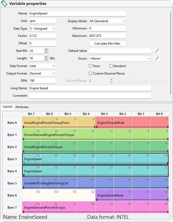
For example, engine speed is defined as PGN 61444 for the Electronic Engine Controller 1 (EEC1), with priority 3, a transmission period of 50 ms, and a data length of 8 bytes.
Data is as shown in the table below, each SPN corresponding to a specific variable name:
| SPN | Name | Factor | Offset | Start Bit | Length |
|---|---|---|---|---|---|
| 4154 | Actual Engine Percent Torque Fract | 0.125 | 0 | 4 | 4 |
| 899 | Engine Torque Mode | 1 | 0 | 0 | 4 |
| 512 | Driver’s Demand Engine Percent Torque | 1 | -125 | 8 | 8 |
| 513 | Actual Engine Percent Torque | 1 | -125 | 16 | 8 |
| 190 | Engine Speed | 0.125 | 0 | 24 | 16 |
| 1483 | Source Address of Controlling Device for Engine Control | 1 | 0 | 40 | 8 |
| 1675 | Engine Starter Mode | 1 | 0 | 48 | 4 |
| 2432 | Engine Demand Percent Torque | 1 | -125 | 56 | 8 |
Each SPN defines the name, scaling factor, and offset. The raw value can be converted to an actual value using these definitions.
For example, engine speed is 16 bits long, and if the raw value read is 17214, then the engine speed is 2151.75 RPM (the standard defines the upper limit as 64255, which is 8031.875 RPM).
This information is ultimately organized into DBC files for describing these parameters, which can be loaded into specific software for automatic decoding and conversion of recorded parameter values.
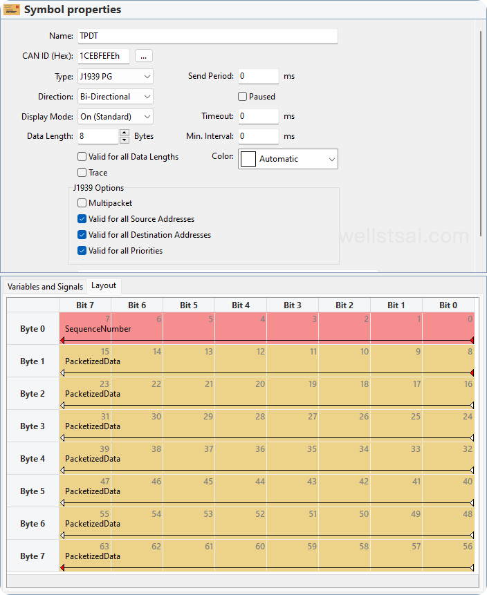
Using the symbol file provided by PEAK-CAN as an example, we can see how the data is presented in these 8 bytes, with SPN, offset, decoding method, and units defined:
Finally, a SPN can exist in multiple PGNs. For example, a manufacturer may define SPN 30000 as firmware information, which can be read and written through PGN 2000 before production and read-only through PGN 20000 after production.
In the J1939 standard, the SPN is not only used to identify parameters during data transmission, but also serves as the unique identifier for suspected faulty components or parameters within the diagnostic trouble code (DTC). To emphasize this diagnostic indication, the standard deliberately retains the term “Suspect” to clearly differentiate between simple measurement parameters and those potentially associated with abnormalities.
Message Types
SAE J1939/21 currently records five types of message types. They are:
- Command
- Request
- Broadcasts/Responses
- Acknowledgement
- Group Functions
Command
Command message types are essentially regular PGNs that support two types of PDU formats: PDU1 for point-to-point communication and PDU2 for broadcast communication. Examples of command types include “Transmission Control,” “Address Request,” “Torque/Speed Control,” etc.
Request
PGN is 0x0EA00. The request message type is used to request specific data (PGN) globally or from a specific target, as shown below:
Upon receiving a request, the receiver must respond, even if it means sending a Negative Acknowledgement (NACK) when the requested PGN does not exist. However, global requests do not trigger NACK if a specific PGN is not supported.
Broadcast/Response
Broadcast/Response message type is a normal PGN supporting two PDU formats, PDU1 for point-to-point communication, and PDU2 for broadcast communication. It can be unsolicited data broadcasts or responses to commands or requests.
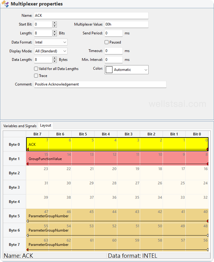
Acknowledgement
PGN is 0x0E800. It provides a handshake mechanism between the transmitting and responding nodes to ensure that commands or requests are properly processed upon receiving responses.
The SAE J1939/21 standard does not explicitly state that the Acknowledgement Message Type supports only the PDU1 format. Thus, the target address can be set to 0xFF, simplifying the data filtering process at the receiver end.
There are four types of ACK, identified by the first byte:
- Byte 0 = 0x00, Positive Acknowledgement (ACK)
- Byte 0 = 0x01, Negative Acknowledgement (NACK)
- Byte 0 = 0x02, Access Denied (PGN supported but access denied for security reasons)
- Byte 0 = 0x03, Cannot Respond (PGN supported but ECU unable to respond, retry later)
Group Functions
Used for manufacturer-specific, assignable PGNs, enabling proprietary functions, network management, and multi-packet transmission functions.
PGN range:
- 0x0EF00 (61184), Proprietary A
- 0x1EF00 (126720), Proprietary A2
- 0x0FF00 (65280) ~ 0x0FFFF (65535), Proprietary B
- 0x1FF00 (130816) ~ 0x1FFFF (131071), Proprietary B2
Transmitting Over 8 Bytes
In traditional CAN, data length is limited to 8 bytes. SAE J1939-21 defines multi-frame transmission methods for transmitting data lengths exceeding 8 bytes, up to a maximum of 1785 bytes.
In the J1939 transport protocol, there are two main methods for handling multi-frame data transmission: point-to-point messages and broadcast messages:
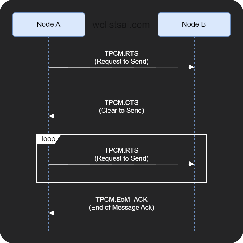
- Request to Send/Clear to Send (RTS/CTS): In the RTS/CTS method, the sender sends a Request to Send (RTS) message to the receiver, asking if data can be sent. The receiver responds with a Clear to Send (CTS) message, indicating readiness to receive data. This method is for point-to-point transmission.
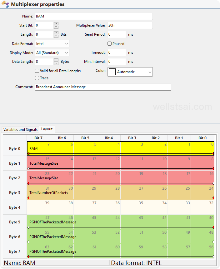
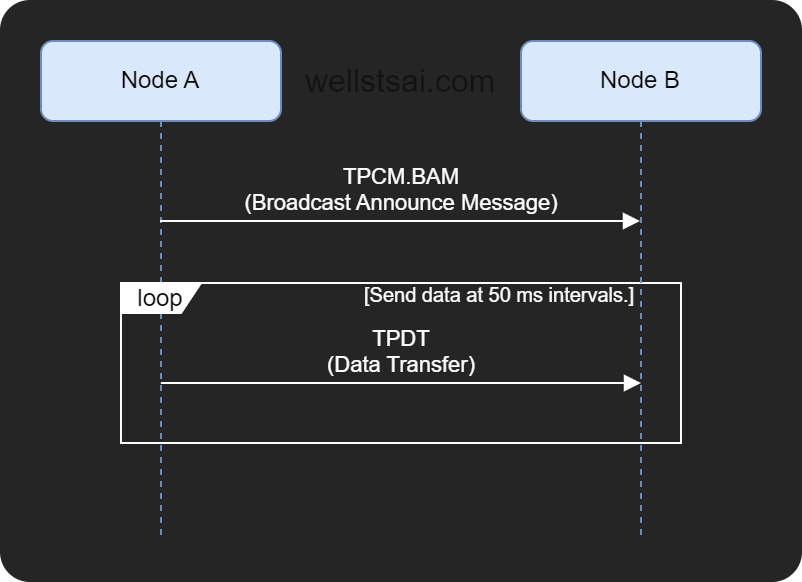
- Broadcast Announce Message (BAM): In the BAM method, the sender broadcasts an announce message indicating that multiple data frames will be sent. This method does not require a response from the receiver, making it suitable for broadcasting to multiple receivers.
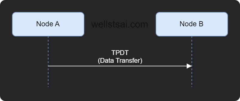
The method of transmission is determined by the Transport Protocol - Connection Management (TPCM) and Transport Protocol - Data Transfer (TPDT) messages.
The corresponding PGNs are TPCM: 0x0EC00 (60416) and TPDT: 0x0EB00 (60160).
TPCM
In TPCM, Byte 0 indicates the type of packet.
| Symbol Name (PCAN) | Byte 0 | Packet Description |
|---|---|---|
| TPCM.RTS | 0x10 (16) | Request to Send (RTS) |
| TPCM.CTS | 0x11 (17) | Clear to Send (CTS) |
| TPCM.EoM_ACK | 0x13 (19) | End of Message Acknowledgment |
| TPCM.ConnAbort | 0xFF (255) | Connection Abort |
| TPCM.BAM | 0x20 (32) | Broadcast Announce Message (BAM) |
TPDT
In TPDT, Byte 0 indicates the sequence number, ranging from 1 to 255. The subsequent 7 bytes carry the data. For very long data, if it is not a multiple of 7, 0xFF is used as padding.
A total of 255 sequences can be transmitted, with each sequence carrying 7 bytes, resulting in a maximum of 1785 bytes of data.
TPCM.RTS
The RTS message notifies a specific node on the network that a virtual connection is requested. The SA of the RTS message is set to the sender’s address, and the DA is set to the intended receiver’s address. The message payload includes the length of the data or the PGN number being requested.
TPCM.CTS
This message is used to respond to an RTS message. The CTS message informs the sender that the receiver is ready to accept a certain amount of data.
TPCM.EoM_ACK
Sent by the receiver to the sender, indicating that the entire message has been correctly received and reassembled.
TPCM.ConnAbort
This can be sent by either the sender or receiver to terminate an incomplete message transmission or to prevent the initiation of a connection. The packet includes the reason for the interruption.
| Abort Code | Connection Abort Reason |
|---|---|
| 0 | Reserved for SAE assignment. |
| 1 | Already in one or more connection managed sessions, cannot support another. |
| 2 | System resources are used for other tasks, thus terminating this session. |
| 3 | Timeout occurred, aborting the connection to close the session. |
| 4 | Received a CTS message while data transfer was in progress. |
| 5 | Maximum retransmit request limit reached. |
| 6 | Unexpected data transfer packet. |
| 7 | Incorrect sequence number (software cannot recover). |
| 8 | Duplicate sequence number (software cannot recover). |
| 9 | Total data length exceeds 1785 bytes. |
| 10–249 | Reserved for SAE assignment. |
| 250 | Use code 250 if the abort reason is not listed. |
| 251–255 | Defined by SAE J1939-71. |
TPCM.BAM
BAM does not specify a target address, so the target address is set to 0xFF, broadcasting to all nodes on the network. It does not require an ACK, simplifying the message transmission process.
The target address must be 0xFF (255), indicating a global broadcast.
Packet Transmission Analysis
Using dual-channel CAN allows for self-sending and self-receiving. The following discusses the case when DP is 0, but note that DP can be 1 indicating extended PGNs.
Single Frame Message Transmission
Transmitting data with a length ≤ 8 bytes. PGN 0xEF00 can be used for point-to-point or global broadcast. PGNs from 0xFF00 to 0xFFFF are for global broadcast.
The packet transmission content is as follows:
| Time Diff (ms) | Symbol | PGN | Hex Data |
|---|---|---|---|
| 0 | PropA | 0xEF00 | 01 02 03 04 05 06 07 08 |
In verification, it was found that even when specifying the target location (DA), if the data length is ≤ 8 bytes, the receiver still decodes this packet, possibly due to PCAN implementation differences. However, if the length exceeds 8 bytes, the receiver will not process the packet if DA does not match.
Multi-Packet Message Transmission
Transmitting data with a length > 8 bytes. It can be divided into broadcast and point-to-point.
For BAM, it broadcasts data globally. Assuming the transmission of 15 bytes:
BAM
The BAM transmission interval ranges from 10 ms to 200 ms [*], with the maximum packet time difference for the receiver being 750 ms. If this time difference is exceeded and more packets are expected but not received, it is considered a timeout and the connection is automatically closed.
| Time Diff (ms) | Symbol | PGN | Hex Data | SA | DA |
|---|---|---|---|---|---|
| 0 | TPCM.BAM | 0xEC00 | 20 0F 00 03 FF FF FF 00 | 248 | 255 |
| 50 | TPDT | 0xEB00 | 01 01 02 03 04 05 06 07 | 248 | 255 |
| 50 | TPDT | 0xEB00 | 02 08 09 0A 0B 0C 0D 0E | 248 | 255 |
| 50 | TPDT | 0xEB00 | 03 0F FF FF FF FF FF FF | 248 | 255 |
From the table, the control value 0x20 indicates BAM, data length is 0x000F (15 bytes), and the number of packets is 0x03. The subsequent TPDT packets start with the sequence number, followed by actual data. If the last packet’s data is not a multiple of 7, it is padded with 0xFF.
- According to SAE J1939-21, the interval after BAM transmission should be at least 10 ms, not 50 ms. Many sources on the internet mention 50 ms, and PCAN’s implementation also uses a 50 ms interval, which might be due to an update in the standard. This has not been explored in detail. According to the latest official standard, the transmission delay should be between 10 ms and 200 ms, with the maximum interval for the receiver being 750 ms.
Point-to-Point (P2P)
Before transmitting P2P data, claim addresses need to be declared. Failure to declare them in advance results in unsuccessful data transmission and may require retransmission, causing increased network load and delays.
| Time Diff (ms) | Symbol | PGN | Hex Data | SA | DA |
|---|---|---|---|---|---|
| 0 | TPCM.RTS | 0xEC00 | 10 0F 00 03 FF FF FF 00 | 248 | 247 |
| 1.5 | TPCM.CTS | 0xEC00 | 11 03 01 FF FF FF FF 00 | 247 | 248 |
| 2 | TPDT | 0xEB00 | 01 01 02 03 04 05 06 07 | 248 | 247 |
| ~ 0.4 | TPDT | 0xEB00 | 02 08 09 0A 0B 0C 0D 0E | 248 | 247 |
| ~ 0.4 | TPDT | 0xEB00 | 03 0F FF FF FF FF FF FF | 248 | 247 |
| ~ 0.4 | TPCM.EoM_ACK | 0xEC00 | 13 0F 00 03 FF FF FF 00 | 247 | 248 |
In the table, the handshake process begins with an RTS (0x10) packet sent to the target address 247. The target responds with a CTS packet, indicating it can receive a number of packets equal to 0x03 and specifying the sequence number of the next packet as 0x01. Data transmission then begins, and upon completion, address 247 sends an ACK packet to confirm the received data length and the number of packets.
If the data length or reception interval is too long (exceeding 750 ms), the receiver will send a timeout message and request data retransmission. In this case, the receiver sends a TPCM.CTS to the sender, requesting specific sequence number packets to prevent session termination.
Additionally, if the sender is too slow, it may cause the receiver to send a TPCM.CTS request for retransmission during the TP.DT transmission process due to timeout. If the sender receives this CTS request, it may interrupt the session due to the established connection (reason: Multi_CTS). Therefore, to avoid session interruption, the sender should ensure the data transmission is completed before the timeout (750 ms). If the sender can complete the transmission of all data packets before receiving the retransmission CTS, the session will continue without interruption.
- RTS Failure
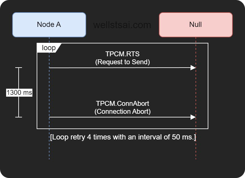
| Time Diff (ms) | Symbol | PGN | Hex Data | SA | DA |
|---|---|---|---|---|---|
| 0 | TPCM.RTS | 0xEC00 | 10 0F 00 03 FF FF FF 00 | 248 | 247 |
| 1300 | TPCM.ConnAbort | 0xEC00 | FF 03 FF FF FF FF FF 00 | 248 | 245 |
| 50 | TPCM.RTS | 0xEC00 | 10 0F 00 03 FF FF FF 00 | 248 | 247 |
| 1300 | TPCM.ConnAbort | 0xEC00 | FF 03 FF FF FF FF FF 00 | 248 | 245 |
| 50 | TPCM.RTS | 0xEC00 | 10 0F 00 03 FF FF FF 00 | 248 | 247 |
| 1300 | TPCM.ConnAbort | 0xEC00 | FF 03 FF FF FF FF FF 00 | 248 | 245 |
| 50 | TPCM.RTS | 0xEC00 | 10 0F 00 03 FF FF FF 00 | 248 | 247 |
| 1300 | TPCM.ConnAbort | 0xEC00 | FF 03 FF FF FF FF FF 00 | 248 | 245 |
When RTS transmission fails, the system retries multiple times, with each retry interval being about 50 ms. If no response is received within 1300 ms, a TPCM.ConnAbort packet is sent to abort the connection, followed by another RTS attempt. This process repeats until successful or the maximum of 3 retries is reached.
Conclusion
This article delves into the main features and mechanisms of SAE J1939, including handling data lengths over or under 8 bytes. Understanding the SAE J1939 protocol is crucial for mastering the operation principles of extended protocols like CANopen, AUTOSAR, and NMEA 2000.
This article does not cover all aspects of J1939, such as network management, address claiming, diagnostics, etc. These topics may be explored in future studies. The information provided should be sufficient to understand and apply the basic concepts and operations of the J1939 protocol.
More advanced topics may involve firmware implementation and integrating existing code, such as the Open-SAE-J1939, which poses practical challenges for application.
References
- Lawrenz, Wolfhard, ed. CAN System Engineering: From Theory to Practical Applications. Springer, 2013.
- Vector. “SAE J1939 Know-how”
- Kvaser. “Higher Layer Protocols”
- ISO. ISO 15765-3: Road vehicles — Diagnostic communication over Controller Area Network (DoCAN) — Part 3: Implementation of unified diagnostic services (UDS on CAN). ISO, 2004.
- SAE International. J1939-21-2022: Data Link Layer. SAE, 2022.
- SAE International. J1939-71-2022: Vehicle Application Layer. SAE, 2022.
- Wilfried Voss. A Comprehensible Guide to J1939. Copperhill Technologies Corporation, 2008.
- Daily, J. (2022). Introduction to SAE J1939: A primer for in-vehicle networking.