What is Controller Area Network?
The Controller Area Network (CAN) is a data transmission protocol used in the automotive field, allowing multiple devices within a network to communicate with each other, providing real-time reliable data transmission. CAN was introduced by Bosch in 1983 and was standardized by the International Organization for Standardization (ISO) in 1993.
The current versions of CAN are:
- CAN 2.0 (1991), also known as Classical-CAN, is the original version with a maximum data rate of 1 Mbps and a maximum payload size of 8 bytes.
- CAN FD (2012), provides a higher transmission rate, with FD standing for Flexible Data Rate. It has a maximum data rate of 8 Mbps and a maximum payload size of 64 bytes.
- CAN XL (2022), offers even higher data rates and larger payload capacities than CAN FD, along with enhanced transmission security. XL stands for Extra Large. It has a maximum data rate of 10 Mbps and a maximum payload size of 2048 bytes.
CAN significantly simplifies communication between electronic control units (ECUs) or different devices, which traditionally required point-to-point communication using UART. By using CAN, the complexity of wiring is greatly reduced, enabling multiple devices to communicate efficiently on a single network, thereby simplifying wiring and enhancing system reliability and efficiency.

Using CAN significantly simplifies wiring and enhances reliability.
Nowadays, CAN communication is widely used in the automotive industry due to its characteristics:
- Low Cost and Lightweight Network: The communication uses a linear bus architecture, reducing implementation costs while keeping the network lightweight.
- Direct Communication Among Multiple Devices: Allows multiple devices on the network to communicate directly without requiring a central host controller, enhancing system flexibility.
- Reliable Real-time Performance: Provides real-time data transmission, making it particularly suitable for vehicle control systems.
- Interference Resistance: Utilizes differential signaling (CAN-High / CAN-Low) to improve resistance to electromagnetic interference, ensuring stable communication in noisy environments.
- Low Power Consumption and Network Wakeup Support: Features low power consumption and supports network wakeup functionality.
- Simple Architecture: Compared to Ethernet, CAN’s architecture is simpler, making system design and maintenance easier.
However, CAN has limitations in terms of transmission speed and the number of nodes, making it unsuitable for transmitting large amounts of data such as images and videos. Additionally, the CAN protocol does not implement encryption, so security measures must be implemented separately when needed.
The main types of data transmitted via CAN include:
- Control commands
- Sensor data (e.g., vehicle speed, steering angle, temperature, gear position)
- Diagnostic messages
- Firmware updates
- Real-time events
Key Points of CAN
Communication is achieved using CAN_H(igh) and CAN_L(ow). When the distance is short enough, grounding (GND) is generally not required.
However, in long-distance transmissions, ground offset can occur, which increases the $V_{cm}$ at certain nodes. If this exceeds the $V_{cm}$ tolerance of the CAN IC, decoding will fail.
To ensure reliable connections, it is recommended to use a common grounding point to avoid decoding failures.
$CAN_H$ and $CAN_L$ are differential signals.
CAN uses differential signals for communication. During this process, noise, known as common-mode signal, can be encountered.
The voltage can be represented as $V_d$ for differential signals and $V_{cm}$ for common-mode signals.
$V_{cm}$ is present simultaneously in both $CAN_H$ and $CAN_L$. The differential amplification (subtraction) within the CAN IC can eliminate common-mode noise.
$V_{cm} = \frac{V_{CANH} + V_{CANL}}{2}$
$V_{d} = (V_{CANH} + V_{cm}) - (V_{CANL} + V_{cm}) = V_{CANH} - V_{CANL}$
According to the datasheet, for a 5 V CAN system, the default output level is 0.5 $V_{cc}$ = 2.5 V (relative to ground for both $CAN_H$ and $CAN_L$).
- Recessive represents a bit value of 1: $V_{CANH}$ = $V_{CANL}$ = 2.5 V, and $V_{d}$ is 0 V.
- Dominant represents a bit value of 0: $V_{CANH}$ = 3.5 V, $V_{CANL}$ = 1.5 V, and $V_{d}$ is 2 V.
- For more detailed voltage information, refer to the datasheet.
CAN transmission uses an arbitration mechanism where dominant signals have higher priority over recessive signals. Therefore, the smaller the CAN ID, the higher its priority. However, if the system is improperly designed, low-priority CAN IDs may face difficulties in transmission.
Dominant signals have higher priority because the CAN transceiver’s circuitry is implemented using wired-AND logic. For more details on the architecture, refer to the datasheet of the CAN transceiver IC.
When node A sends a dominant signal (0) and node B sends a recessive signal (1), node B will detect a collision and stop transmitting, switching to receiving mode. The Carrier Sense Multiple Access with Collision Avoidance (CSMA/CA) mechanism will automatically retransmit when the network is idle, avoiding collisions.
If you do not know which line is $CAN_H$ or $CAN_L$, you can use a multimeter to measure the average voltage or an oscilloscope for evaluation. The average voltage of $CAN_H$ will be higher than 2.5 V, while $CAN_L$ will be lower than 2.5 V ($V_{cc}$ = 5 V).
Each CAN transmission is called a frame, and a frame mainly includes the target ID, length, and data content. For more details, refer to the Frame Format.
The CAN network consists of:
- Microprocessor (MCU): Responsible for data processing and application layer logic. It includes an integrated CAN controller, allowing the MCU to directly handle CAN communication. When necessary, the MCU relies on functions provided by the CAN controller to implement higher-level protocols.
- CAN Controller: Handles the formatting of data packets, arbitration, error detection, and other tasks related to the CAN protocol.
- CAN Transceiver: An independent IC responsible for converting the TTL voltage levels of the MCU into differential signals on the CAN network, and vice versa for the MCU to receive. It converts the MCU’s TX and RX to the $CAN_H$ and $CAN_L$ differential signals.
- CAN Network: Composed of two differential signal lines, $CAN_H$ and $CAN_L$, used for data transmission.
The CAN network endpoints have termination resistors (120 Ohms) to reduce reflection waves on the transmission line. Refer to: Design and Considerations of Termination Resistors.
- Using a multimeter to measure $CAN_H$ and $CAN_L$ in the CAN network, the equivalent network resistance should be around 60 Ohms (approximately 55 Ohms to 65 Ohms).
- If it measures 0 Ohms to 5 Ohms, $CAN_H$ and $CAN_L$ may be short-circuited.
- If it measures 30 Ohms to 50 Ohms, there may be extra termination resistors or incorrect resistor values in the network.
- If it measures 110 Ohms to 140 Ohms, one termination resistor may be missing from the network (normally two termination resistors in parallel equal 60 Ohms).
- If it measures 1 kOhms to 10 kOhms, two termination resistors may be missing from the network.
- If it measures more than 10 MOhms, the CAN physical line is disconnected.
There is a probability of packet loss in CAN communication, and it is recommended that the overall load does not exceed 60-70% (rule of thumb).
The maximum data rate for CAN 2.0 is 1 Mbps, while CAN FD can achieve data transfer rates up to 8 Mbps.
Transmission rates are categorized into two types: nominal bit rate (NBR) and data bit rate (DBR).
In CAN 2.0, the arbitration phase and data phase share the same rate, so there is no distinction between the rates. Commonly mentioned speeds like 500 kbps or 1 Mbps refer to the overall CAN communication speed.
In CAN FD, both NBR and DBR are defined. The arbitration phase can use 500 kbps or 1 Mbps NBR to maintain compatibility with traditional CAN. In the data phase, DBR can reach up to 5 Mbps for data transmission.
The CAN FD controller is backward compatible with CAN 2.0 packets.
However, the CAN 2.0 controller cannot process CAN FD packets. The reason lies in the differences in the headers of the two types of packets. When a CAN 2.0 controller receives a CAN FD packet, it will respond with an error frame because certain bit configurations in the CAN FD packet do not conform to the CAN 2.0 standard.
Even if the arbitration bit rate (nominal bit rate, NBR) and the data bit rate (data bit rate, DBR) of CAN FD are both set to 500 kbps, the CAN 2.0 receiver still cannot decode CAN FD packets.
Glossary of CAN Terms
| Term | Description |
|---|---|
| Standard CAN | CAN 2.0 standard format, also known as CAN 2.0A, uses 11 bits to represent the ID. |
| Extended CAN | CAN 2.0 extended format, also known as CAN 2.0B, uses 29 bits to represent the ID. |
| CAN FD | Flexible Data-Rate CAN, can use 11 or 29 bits for the ID and supports up to 64 bytes of data length. It features higher data transfer rates, reducing CAN load by transmitting more data in a single frame. |
| CAN XL | Third-generation CAN protocol, with a longer data length (2048 bytes) than CAN FD. |
| FlexCAN | An IP module by NXP, implementing both CAN FD and CAN 2.0B protocols, compliant with ISO 11898-1 standard. |
| MCAN | An IP module by TI, implementing CAN FD and compliant with ISO 11898-1 standard. |
| MCMCAN | A module by Infineon, replacing their MultiCAN. Supports both traditional CAN and CAN FD. |
| Vector | A German company providing solutions for automotive and embedded systems. |
| CANoe | A tool by Vector for CAN software development and testing. It can generate signals and simulate communication behavior. The simplified version is CANalyzer. |
| CANape | A tool by Vector used for measuring, calibration, and diagnostics of electronic control units (ECUs) and advanced driver-assistance systems (ADAS). |
| Peak-System (PCAN) | A German company providing solutions for automotive and embedded systems. |
| XCP | Universal measurement and calibration protocol, allowing external devices (like calibration tools or measurement instruments) to communicate with embedded systems for parameter adjustment, performance evaluation, and fault diagnosis. |
| UDS | Unified Diagnostic Services, a communication protocol used in vehicle diagnostic systems for communication and information exchange. It defines standard services and diagnostic protocols to ensure effective communication between diagnostic tools and vehicle control units (ECUs). |
| OBD-II | A standard protocol allowing external electronic devices to access the vehicle’s internal computer systems for diagnostics and emissions testing. Typically seen as a 16-pin (2x8) SAE J1962 female connector in vehicles. |
| .dbc | CANdb database file, developed by Vector, an industry standard widely used in CAN-related software. Describes details such as IDs, names, and lengths on the CAN network. |
| CiA | CAN in Automation (CiA) is an international users’ and manufacturers’ organization that develops and supports higher-layer protocols based on CAN and their international standardization, addressing areas not covered by the CAN protocol itself. |
| CANopen | A high-level communication protocol based on CAN, suitable for embedded applications. It extends CAN’s capabilities, supports larger data packets, and provides rich communication features for complex machine automation applications. Developed and maintained by the CiA. |
| AUTOSAR | AUTomotive Open System ARchitecture (AUTOSAR) is a global open standard aimed at developing software architecture for automotive electronic systems. It is created by automotive manufacturers, suppliers, and software companies to provide a scalable and reusable software platform to address the increasing complexity of automotive electronic systems. |
| DeviceNet | A high-level communication protocol based on CAN, primarily used in factory automation for communication between controllers (PLCs) and industrial I/O devices (like limit switches, sensors, drives, displays, and operator interfaces). Maintained by the Open DeviceNet Vendor Association (ODVA). |
| SAE J1939 | A high-level communication protocol based on CAN, primarily for vehicle applications. It allows extensive data exchange within vehicle systems, supports messages of unlimited length, and supports master/slave architecture, suitable for complex vehicle communication needs. A standard set by the Society of Automotive Engineers (SAE). |
| CanKingdom | A high-level communication protocol based on CAN, specialized for distributed control systems in industrial and embedded applications. Designed to provide a flexible and efficient communication architecture for higher-level collaboration and management in systems using the CAN protocol. |
| recessive bit | The logical bit 1 in CAN signaling. |
| dominant bit | The logical bit 0 in CAN signaling. |
Data Frame Format
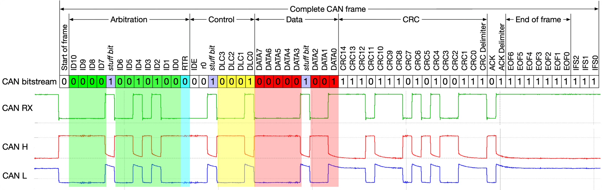
Start of Frame (SOF): This flag indicates the beginning of a data frame. Before a CAN node starts, it checks for 11 consecutive bits of ‘1’ to ensure the entire network is idle.
Arbitration Field (12 or 32 bits)
- Base ID: 11 bits
- Remote Transmission Request (RTR): Rarely used in practical applications.
- Extended CAN: Adds the Substitute Remote Request (SRR), IDE flag, and Extended ID (18 bits).
Control Field (6 bits)
- Identifier Extension (IDE) Flag: ‘0’ for CAN 2.0A.
- Reserved Bit (r0): Default to ‘0’.
- Data Length Code (DLC): Uses 4 bits to indicate the length of the subsequent data.
Data Field: Uses 1 to 8 bytes to convey data.
CRC Field (16 bits): Includes a 15-bit CRC sequence and CRC delimiter.
Acknowledgement Field (2 bits): Contains ACK slot and ACK delimiter. If the CRC matches, the ACK slot is set to ‘0’. The ACK delimiter is always ‘1’.
End of Frame (EOF, 7 bits): Marks the end of the frame with 7 bits of ‘1’.
Interframe Space (IFS): Fixed at 3 bits of ‘1’ to ensure enough time between adjacent frames for error handling and synchronization.
- Each message frame ends with 11 bits of ‘1’, including ACK delimiter, EOF, and IFS. Nodes check for these 11 bits at the new SOF to determine if the network is idle. The SOF flag helps synchronize nodes.
- From SOF to CRC, only up to 5 consecutive identical bits are allowed. If there are 5 consecutive bits of ‘0’ or ‘1’, a stuff bit of the opposite value is inserted for signal synchronization and reliability.
Features and Differences of CAN FD
CAN FD is an improvement over CAN 2.0, focusing on:
- Transmitting more data per frame to reduce CAN bus load.
- Higher data rates.
- The CAN FD controller is backward compatible with the CAN 2.0 standard. However, the CAN 2.0 controller cannot process CAN FD packets.
- Support for 11 and 29-bit IDs.
- Removal of the remote frame, replacing RTR with Remote Request Substitution bit (RRS), always set to ‘0’.
- Renaming the r0 bit to FD frame (FDF), fixed at ‘1’.
- Using the Bit Rate Switch (BRS) flag to determine whether data is transmitted at a higher data rate (DBR). If BRS is ‘0’, the bit rate (NBR) is the same as CAN 2.0.
- Error Status Indicator (ESI), ‘0’ for normal operation, ‘1’ for error passive mode.
- Stuff bit count (SBC) uses three Gray codes and one parity bit for enhanced communication reliability.
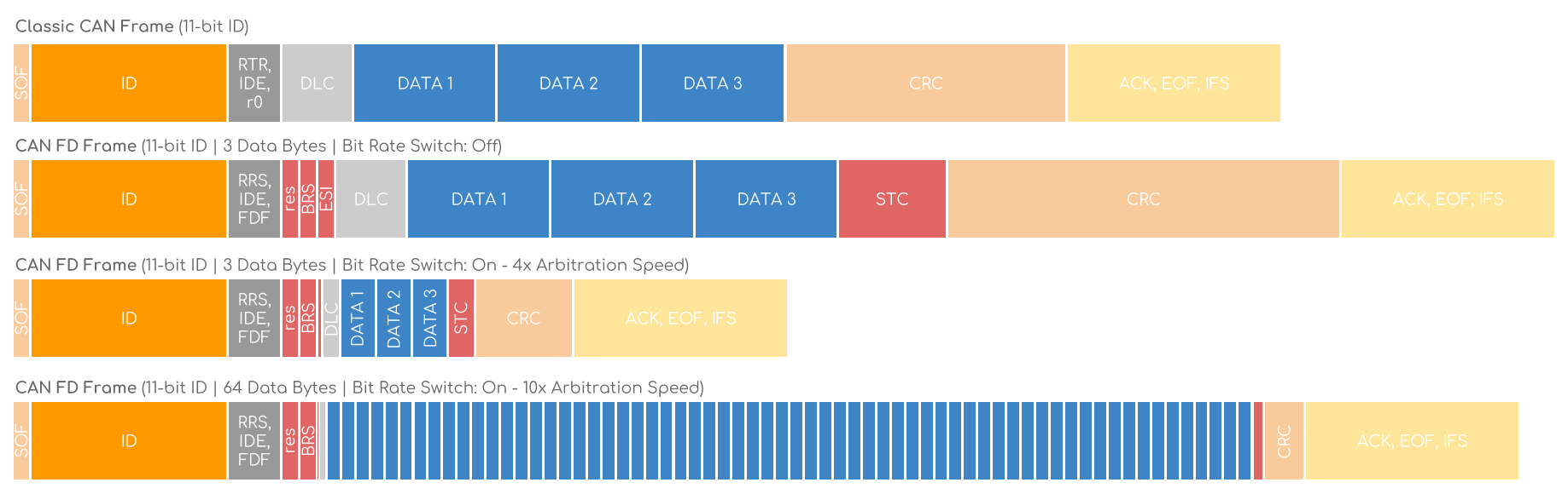
The image above shows that with the same data, if BRS is off, the bit rate follows NBR as in CAN 2.0. With BRS on, data can be transmitted at up to 8 Mbps. The DBR used in the example is 4 and 10 times the NBR.
Bit Timing
Bit timing ensures correct synchronization and communication on the CAN network. It involves configuring time parameters to ensure all nodes can transmit and receive data correctly.
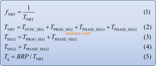
Bit Structure
For a configured CAN rate, such as 500 kbps NBR, it means transmitting 500,000 bits per second. The reciprocal of the transmission rate gives the bit time, referred to as Tb or Tnbt.
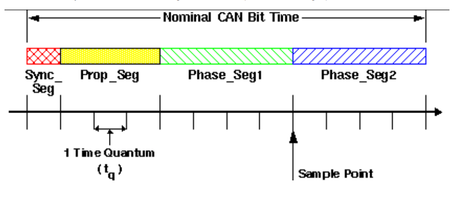
A bit time is divided into four segments:
- Synchronization Segment (SYNC_SEG)
- Propagation Time Segment (PROP_SEG)
- Phase Buffer Segment 1 (PHASE_SEG1)
- Phase Buffer Segment 2 (PHASE_SEG2)
At a transmission rate of 500 kbps (NBR), Tb equals 2 microseconds (Formula 1). The sum of these four segments equals one Tb (Formula 2).
The propagation time segment must consider Node A’s processing time, transmission time, and Node B’s processing time.
Therefore, the propagation time segment must be at least: twice the physical transmission delay plus Node A’s processing time plus Node B’s processing time.
When Node A transmits SOF, it ensures that the CAN arbitration priority mechanism is satisfied.
Time Quantum (Tq)
Tq is the smallest time unit used in CAN bit timing and can be used to evaluate the basic unit of CAN bit timing. It is typically measured in nanoseconds.
Bit time is divided into four segments, with each segment’s length represented using the smallest time unit (Time Quantum, Tq).
For a device with an 80 MHz clock, Tq = 1 / 80 MHz = 12.5 ns.
If the CAN FD data bit rate (DBR) needs to be set to 5000 kbps:
Configure Tsync_seg = 1 (fixed), Tseg1 = 13, and Tseg2 = 2. The total Tq is 16 units.
12.5 ns × 16 = 0.2 µs, which means one bit is 0.2 µs. The reciprocal of this value gives a data rate of 5000 kbps.
Baud Rate Prescaler (BRP)
Devices have different internal clocks, and the BRP within the device can be used to divide the clock frequency to adjust Tq.
For example, if the device clock is 80 MHz, then Tq is 12.5 ns.
If BRP is set to 2, the clock frequency is divided to 40 MHz, making Tq 25 ns.
Sample Point
The sample point within a bit time determines whether the state on the CAN network is ‘0’ or ‘1’.
According to industry standards such as CANopen and DeviceNet, it is recommended to use an 87.5% sample point for CAN. This recommendation is because an 87.5% sample point provides a good balance between network length and oscillator tolerance.
Synchronization Jump Width (SJW)
SJW is used to compensate for oscillator tolerance. It works in conjunction with Phase Buffer Segments (Phase_Seg1 and Phase_Seg2) to ensure synchronization on the CAN bus.
In a CAN system, the frequency of the oscillator may vary due to temperature changes, voltage fluctuations, or component aging.
To ensure stable communication between different nodes, the phase buffer segments and SJW are used to compensate for phase shifts caused by oscillator tolerance.
This value is independent of NBR and DBR and primarily provides tolerance for clock drift, typically set to 1 to 2 Tq.
Calculating Segment Time
Considerations include:
- MCU IC Clock
- Bit Rate (NBR / DBR)
- Transmission Line Delay
- CAN IC Delay
- Temperature (uncontrollable)
Known values:
- Bit Rate (NBR / DBR)
- System Clock (MCU may be 8 MHz / 20 MHz / 40 MHz / 80 MHz)
A preliminary assessment can be done using a calculator. Based on the selected sampling rate (commonly 75% ~ 90%, 87.5% is recommended for evaluation),
you can determine the required prescaler, TSEG1, and TSEG2.
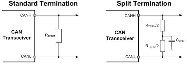
Design and Considerations of Termination Resistors
Standard Termination
As previously mentioned, both ends of the CAN network require 120 Ohm termination resistors, a value that complies with ISO 11898-2 standards. With resistors placed at both ends, the total input impedance observed from either endpoint is the result of the two termination resistors connected in parallel, yielding an overall impedance of approximately 60 Ohms. In a power-off state, the resistance between $CAN_H$ and $CAN_L$ can be measured with a multimeter, with a target range between 45 and 65 Ohms.
According to ISO 11898, the maximum transmission rate for a CAN network is 1 Mbps, with a total bus length not exceeding 40 meters. The stub length should be limited to 0.3 meters, and the maximum number of nodes is capped at 30.
To support more complex network configurations, proper network design can minimize signal reflection effects, enabling the network to support longer main lines, extended stub lengths, and additional devices.
Example: Consider a CAN network with 120 Ohm termination resistors at each end. If eight additional devices are connected with longer cabling between them, a termination impedance of 2.6 kOhm for each device may be considered to maintain the required overall network impedance. In this case, the total impedance is calculated as follows:
| |
According to ISO standards, each end of the CAN network should be equipped with 120 Ohms termination resistors.
In a laboratory setting:
For shorter testing distances, communication is typically unaffected whether the stub-end resistors are present or not. Signal reflection quality is generally better in a lab setting, making it difficult to observe actual effects. Signal evaluation is eventually performed within the entire vehicle network to ensure overall communication stability.
Split Termination
Using an RC filter composed of split resistors can filter out high-frequency noise:
This consists of two equal resistors (60 Ohms) in series to ground, with a 4.7 nF capacitor in parallel to ground at the midpoint, effectively acting as a low-pass filter. This improves noise immunity and reduces electromagnetic radiation.
The cutoff frequency, $f_c = 1/(2πRC)$, calculates to approximately 1.12 MHz ($R_t$ = 30 Ohms), meaning signals above this frequency will be filtered out.
PCAN-View Send and Receive Test
This section explains the basic setup of PCAN and clarifies the parameters and their corresponding interfaces described in the previous chapters.
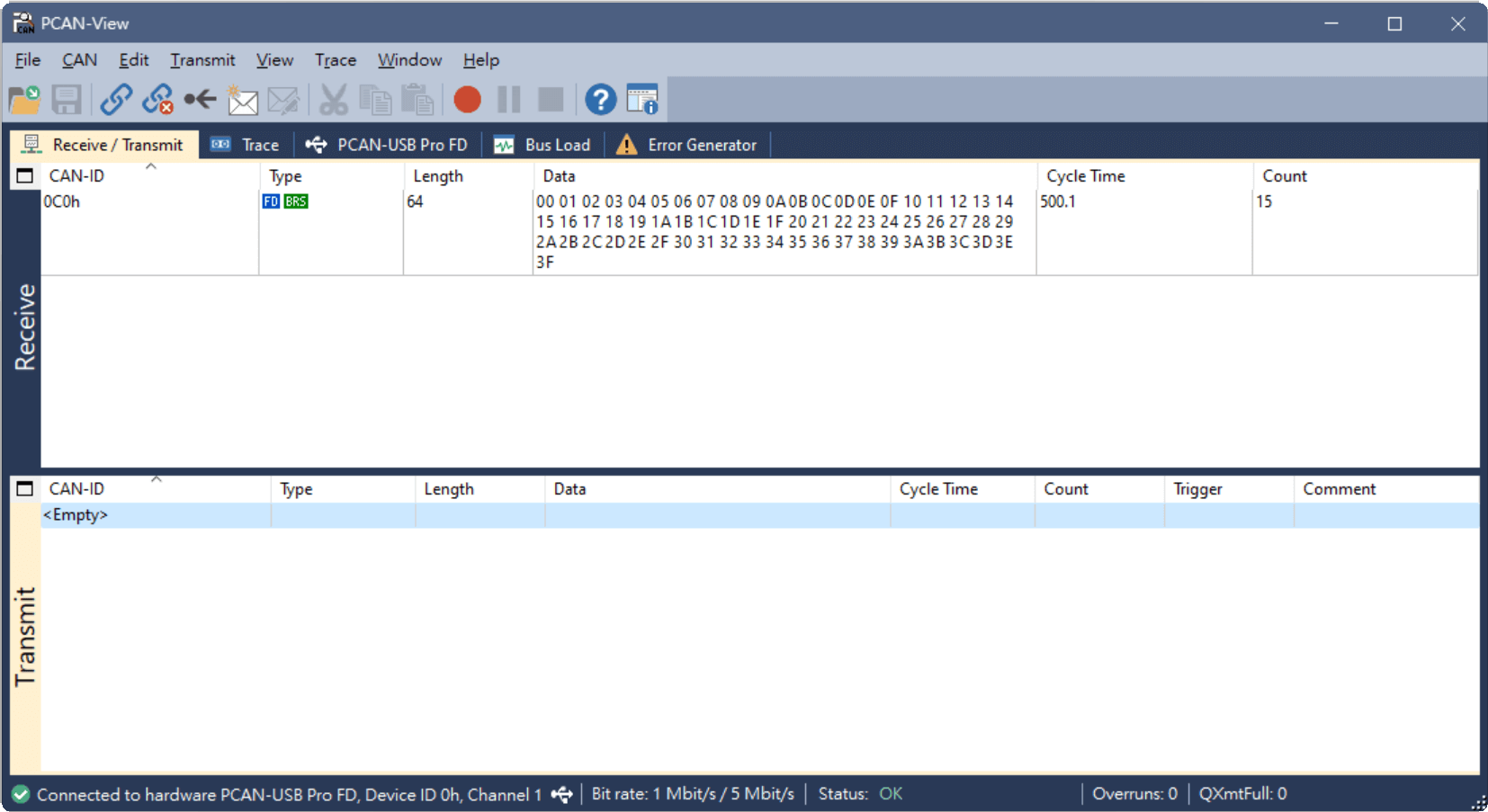
Open PCAN-View. The upper section is the receiver, and the lower section is the transmitter.
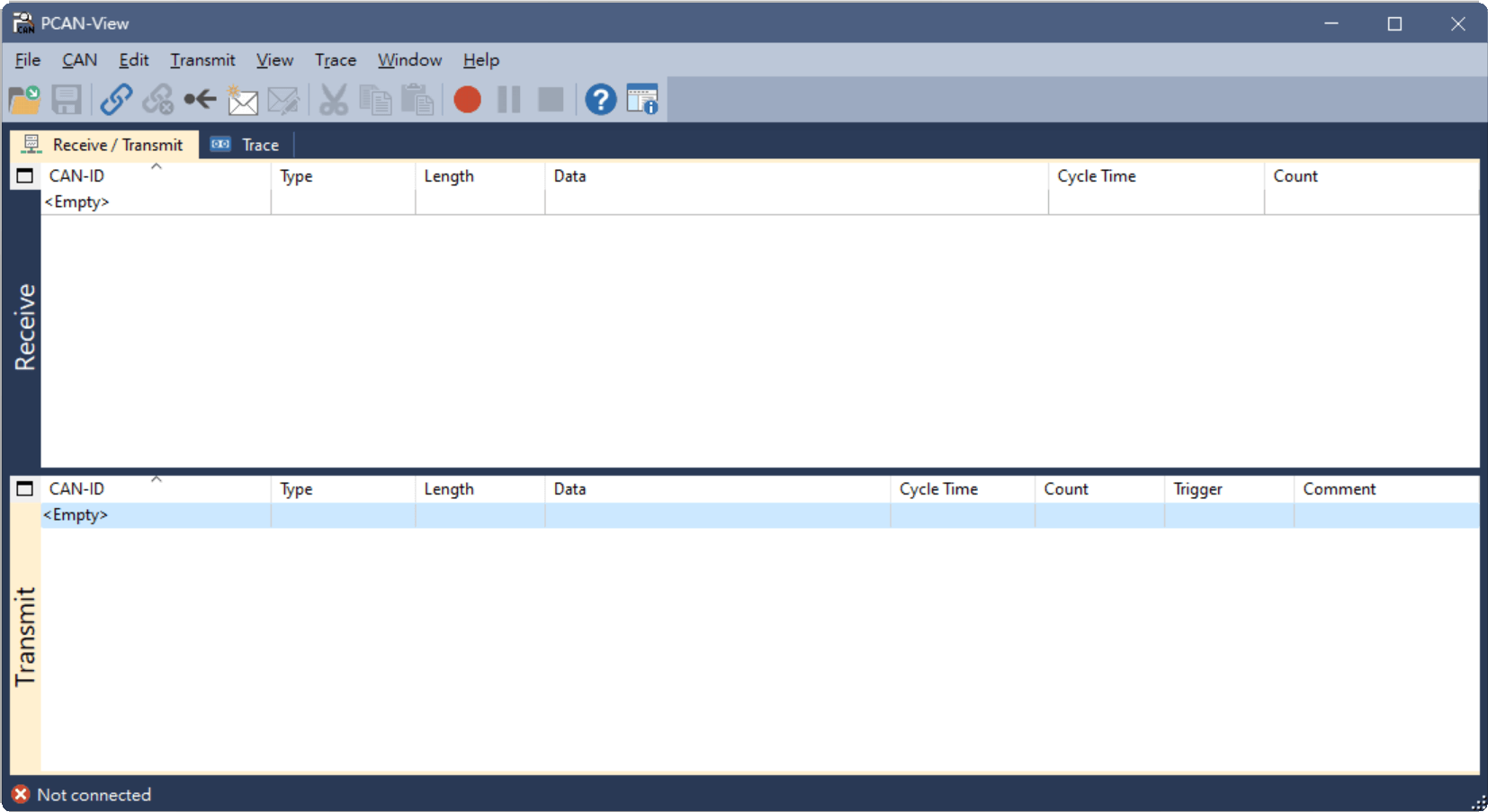
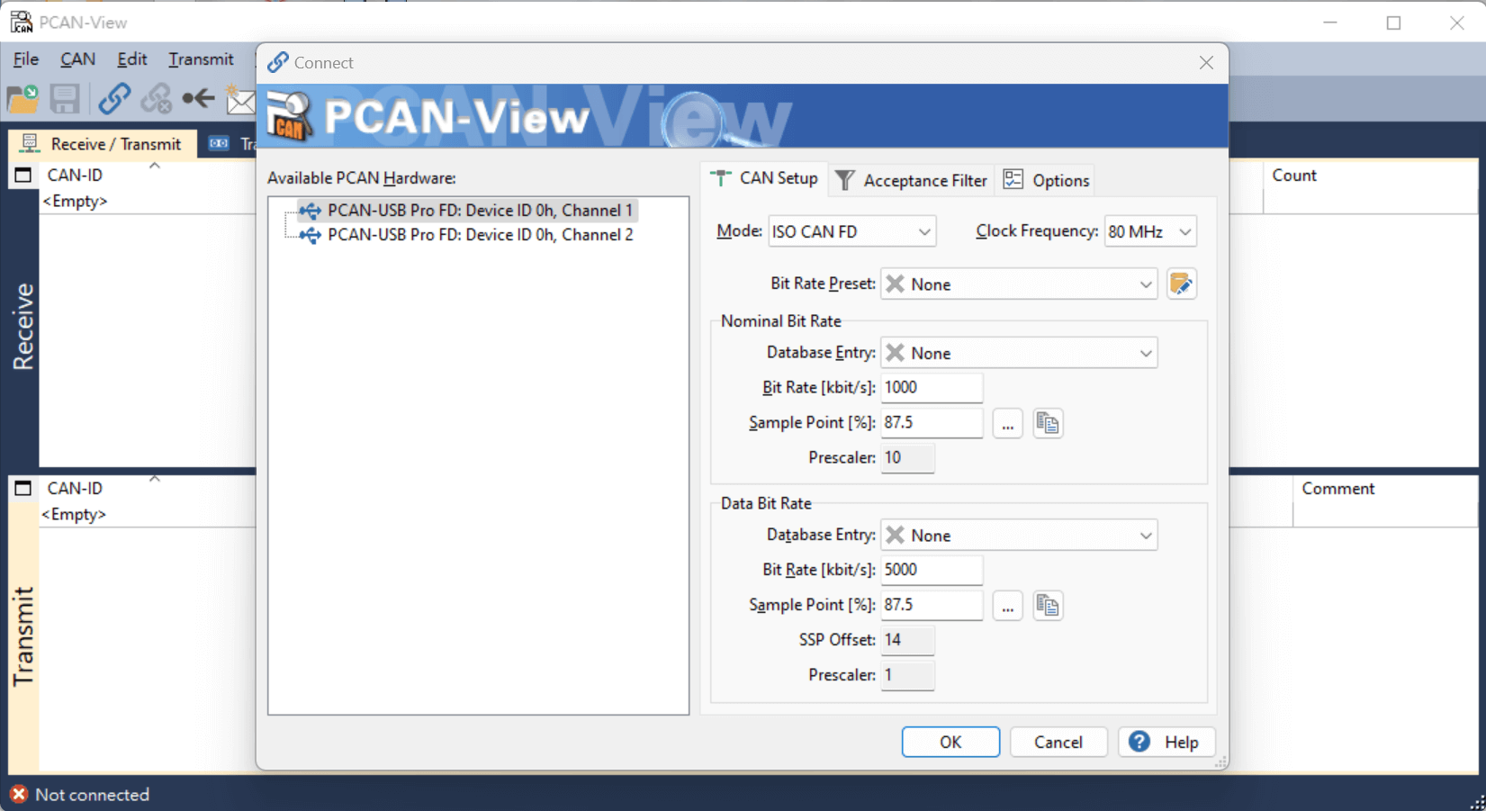
After inserting the hardware, click the connection icon at the top left to access the device settings.
Here, we use CAN FD, with NBR and DBR set to 1000 kbps and 5000 kbps, respectively. The sampling point is set to 87.5%.
After configuring the device, the MCU is currently set to send data every 500 ms. You can see the ID 0xC0 appearing in the Receive section.
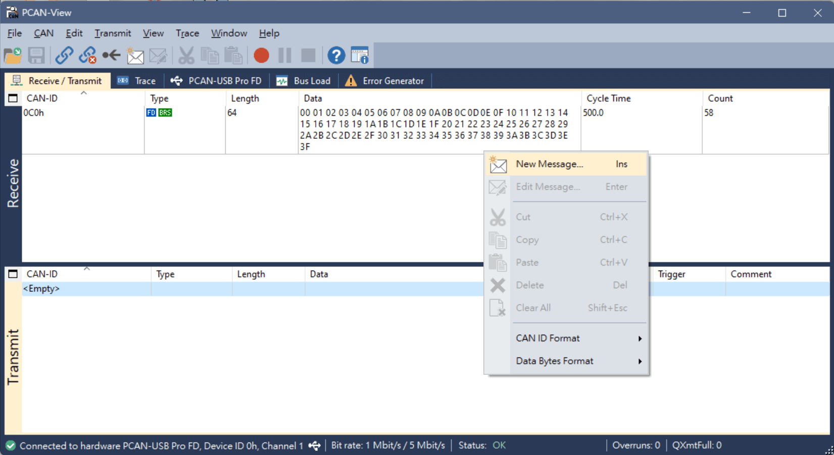
To send data to the MCU, right-click on the blank area in the Transmit section and select “New message…”.
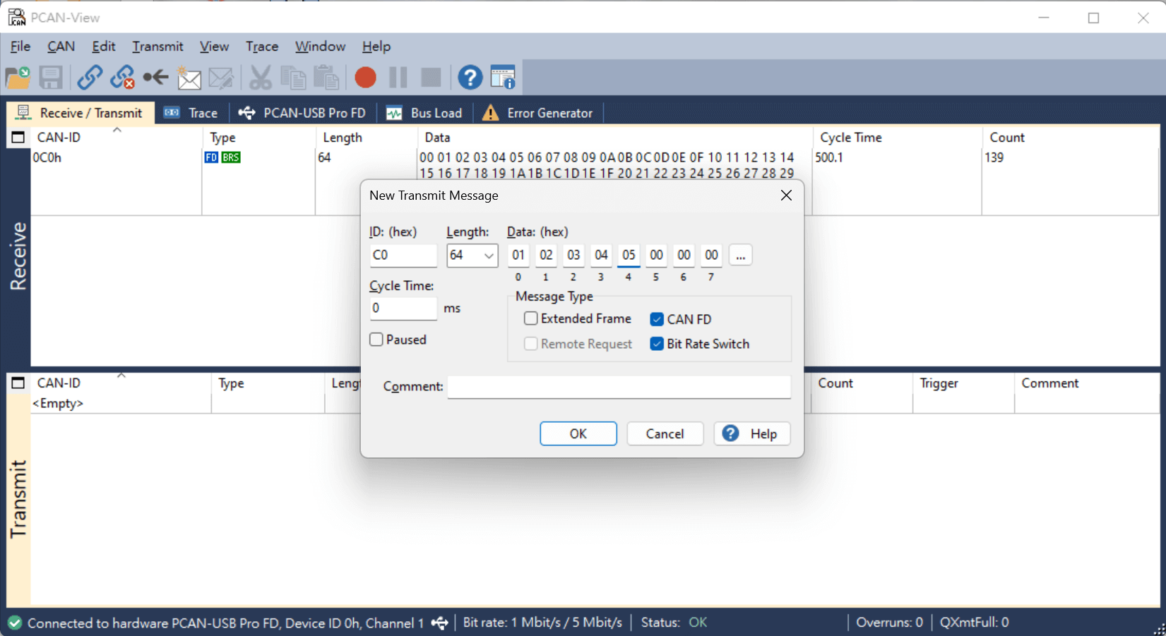
Set the data type to CAN FD and enable BRS to speed up data transmission. The data length is set to 64 bytes.
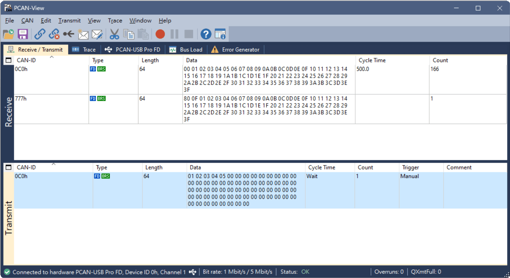
After adding, select the message under the Transmit section and press the space bar to send the message. The MCU will return 0x777 upon receiving the data.
References
- History of CAN technology
- FlexCAN控制器
- Getting Started with the MCAN (CAN FD) Module
- Introduction to the Controller Area Network (CAN)
- Basics of debugging the controller area network (CAN) physical layer
- TJA1040 high speed CAN transceiver
- Practical tips: CAN-Bus
- SN65HVD23x 3.3-V CAN Bus Transceivers
- ISO 11898-1:2015 - Road vehicles
- ISO 11898-2:2016 - Road vehicles
- XCP (protocol)
- Unified Diagnostic Services
- CAN bus
- Learning Module CAN
- CAN FD Explained
- Calculator for CAN Bit Timing Parameters
- The Configuration of the CAN Bit Timing
- CAN Bit Timing Requirements
- Top Design Questions About Isolated CAN Bus Design
- How To Properly Wire A CAN Bus
- A CAN Physical Layer Discussion
- CAN BUS Troubleshooting Guide
- Rules and recommendations for in-vehicle CAN networks